
Networks and Distributed Systems
Research group of Prof. Peter Bernard Ladkin, Ph.D.

Analysis of Data Discontinuities
Michael Blume, Dominic Epsom, Heiko Holtkamp, Peter B. Ladkin and I Made Wiryana
RVS-Occ-99-01
Implementing data structures on real computers can involve mathematical compromises. We describe the kinds of compromise and problems that can arise when the implementation is not chosen wisely. We devise a list of criteria to be fulfilled for an implementation to be regarded as adequate. Verifying these criteria ensures that an implementation is correct. We illustrate with date discontinuity problems epitomised by the various Year 2000 problems.
Contents
- Data Structures, Exemplified by Dates/Times
- Implementing Data Structures
- Representing Data Structures
- Preserving Structure
- Iterated Representation
- Some More Problems
- Verification Conditions
Back to Contents
Data Structures, Exemplified by Dates and Times
In computing, the term data structure is used of such collections of objects as whole numbers, integers, real numbers, strings of characters and suchlike, which have some mathematical structure, and with which programs calculate. What kinds of `structure' are common? For example, a number can be greater or less than another number, so the numbers can be put in order. This is what mathematicians call an ordered structure. Further, since any number is greater than or less than some other, different, number, this ordering is called linear - like the ordering of points on a line which has a direction. Strings of characters can also be ordered, in more than one way: strings be longer or shorter than others, so they can be ordered by length. But two different strings can have the same length, so this ordering is not linear. For a different order on strings of characters (or "words"), consider that characters have an order from "a" to "z", and so words can be ordered as they are in a dictionary, in so-called lexicographic order.
Other, more complex, data structures can be constructed out of simpler ones: sentences are strings of words, although not all strings of words are sentences; sets of numbers such as the even whole numbers can be formed, and so on. One of the most common complex data structures is that of dates and times. We shall use this structure to illustrate what problems can arise when implementing data structures on (real) computers, and we shall illustrate these problems with examples from the collection of so-called Year 2000 problems.
So, first a few words on dates and times. What is the `mathematical structure' of dates and times? We have calendars such as the Gregorian for labelling days, and the twenty-four hour clock, with each hour broken into sixty equal minutes, broken respectively into sixty equal seconds, each of which is broken into tenths, and so on using decimal divisions ad infinitum - or at least potentially. One needs to know not only which particular second of which minute in which hour on which day in which month and year precedes or follows which other second of which ...(etc), but often one also wants to talk about the length of time between one particular time and another. Although everyday talk about time refers to intervals (years, months, days, hours minutes and seconds are all intervals, as are the decimal subdivisions of seconds), physicists and engineers represent `time' as a collection of points (usually the real numbers), not intervals, and measure the passage of time by subtracting one time point number from another: the length of time between "2" and "3.5" is 1.5 (seconds? minutes? hours? well, in whatever unit of time you're using).
Need one choose between these structures? Not really. The interval representation of (real, calendrical) time was formulated in the Time Unit System (TUS) in the thesis of Peter Ladkin, The Logic of Time Representation. It was shown there that the TUS is mathematically equivalent to (`isomorphic to') the structure obtained by constructing intervals out of two time points: in notation <2,3.5>, meaning the interval between `2' and `3.5' (with no time units such as seconds or minutes specified); and the "length" of this time interval is 1.5 (in whatever unit, minutes, seconds or what have you, that you're using). We shall describe the TUS briefly below.
Before introducing the TUS, we should introduce the notion of `sequences'. A word like "fish" consists of four characters, "f" "i", "s", "h" written one after the other. We say that this word is a "string", of `sequence' of characters. When an individual element consists not just of a single character, but itself is a word or suchlike, we use punctuation to mark the boundaries of elements. For example, the notation [199, 3, 21] refers to the sequence with three elements, "199", "3", "21" in that order. Strings and sequences are really the same thing - one is written without punctuation (but could be written with), and the other contains punctuation. The punctuation has no meaning itself, but merely serves to mark the boundaries between elements of the sequence.
The TUS represents time intervals as sequences of non-negative whole numbers, such as [1999, 3, 21] for the 21st March, 1999. The international standard for representing dates, ISO 8601 (1988), requires such a representation for dates, but uses hyphens to mark element boundaries instead of commas (and omits the square parentheses): 1999-03-21. This is just a notational difference. The TUS goes further, using the notation [1999, 3, 21, 11, 34, 57] for the interval consisting of the 57th second of the 34th minute of the 11th hour on the 21st March, 1999. Other intervals may be denoted by giving intervals which start and end them; so that the interval between 11:34 and (the beginning of the interval) 11:59 on this date would be specified in TUS notation by convexify([1999, 3, 21, 11, 34], [1999, 3, 21, 11, 58]) (the word "convexify" just means "make an interval between"). It looks complicated, but it is neither more nor less complicated than the system of dates/times we use in everyday life, and it has the added advantage of being mathematically rigorous. And, as was shown in the thesis of Ladkin, it is mathematically equivalent to the intervals that physicists and other sciences use, so really all these representations are `the same', so to speak.
Back to Contents
Implementing Data Structures
Computer hardware works with basically just five data structures - sequences of 4, 8, 16, 32 or 64 0's and 1's. These data can be thought of as representations of positive whole numbers in binary notation for the purpose of talking about them. Furthermore, there are only a fixed number of them - for 8 bits, all numbers from 0 to 255 (1 less than the 8'th power of 2); for 16 bits, all numbers from 0 to 65,535; and so on for 32- and 64-bit numbers. So every data structure that one can deal with on a computer must somehow be `coded' as a collection of these numbers. This coding must include the `structure' - that is, however the interval <2, 3.5> is coded, it must be possible to determine from the code that its length is 1.5; however [1999, 3, 21] is coded, that its length is one day; or for [1999, 3, 21, 11, 34, 57] that its length is one minute; and that the minute [1999, 3, 21, 11, 34, 57] is part of the day [1999, 3, 21]. The `length' of a bit sequence is always a whole number, as is the hardware `difference' between them, so the `length' of a time interval cannot be the same as either of these, since it can be fractional (for example, 1.5), and it is probably more complicated - it, too, must be `coded'.
One might wish for this coding to be perfect, that is, that the data structure should be mathematically equivalent to its `coding' in the collection of 64-bit sequences. Unfortunately, that's not generally possible. There are infinitely many whole numbers, for example, but only a finite number of 64-bit sequences. But, one may think, we never need all the numbers, just sufficiently many of them. Indeed, that is why desktop computers have progressed from an 8-bit basis to 16 bits, to 32 bits and now to 64 bits: that there should be enough bit-sequences around to do all that a collection of tasks or programs needs.
But programs aren't always translated directly into hardware. Sometimes they are translated (by `compilers') into programs in a simpler language, which is itself translated, and so on. Source programs may go through many stages of translation. The concepts we use will be valid for any translation, although we shall illustrate them assuming that the target of translation is hardware. The issues we describe must be attended to for each translation step of a program, to be assured that it is going to treat data properly.
How can one determine that a coding is `perfect' on `the data that one needs'? We shall now introduce the mathematical formulation of this requirement in pictures, and see what can go wrong.
Back to Contents
Representing Data Structures
We shall introduce the mathematical terminology piecewise. First, suppose one wishes to talk about or calculate with a date [1999, 3, 21]. It must be implemented in the computer ultimately as a sequence of bits. Preferably, it will be represented by only one sequence, since for one date one only needs one representation of that date, and if there were more then one would be using up more bit sequences than needed and as we have seen we have only a finite number, whereas the set of dates is potentially infinite. The first principle, then, is that to one date corresponds one representation. We say that the relation of representing is a function. Figure 1 shows a relation, with the data structure DS to the left (individual elements are points), the representation DR to the right, with lines connecting elements and their representations. If one eliminates connections marked with an "X", the relation becomes a function, as required. We shall call this function DRep (for `DatumRepresentor').

Figure 1: A Relation that is Not a Function
One-To-One
Second, since the computer is calculating with sequences of bits rather than dates, but nevertheless the dates are the real meaning of the bits to the program, the machine must `know' which sequence of bits means which date. That is, any sequence of bits should represent a unique date, otherwise one may miscalculate all sorts of things. For example, if one bit sequence represents both Monday, January 4th, 1999 and Monday, January 11th, 1999, then the number of days between that `date' and Thursday, January 7th would be either 3 days or 4 days and there would be no way to determine which was `correct' - because both are possible, since the bit sequence has two meanings, two dates with which it can correspond. Such ambiguity can only lead to confusion. So unambiguity requires that to each representation correspond only one date. This is the requirement of being a `function in reverse', if you like. Mathematicians say that the function is one-to-one if it satisfies this condition. The diagram below in Figure 2 does not represent a one-to-one function, but if one were to eliminate the connection marked with an "X", it would be. (However, there would then be a datum that had no corresponding representation on the right, which leads to other problems.)

Figure 2: A Function that is not One-to-one
The diagram below in Figure 3 does represent a one-to-one function; moreover, one for which every DR item corresponds to some DS item. The function is said to be "onto". A one-to-one onto function, as in Figure 3, is called a "bijection".

Figure 3: A One-to-one Function
By rearranging the picture of the elements on the right-hand side (in the `range' of the function), one can always draw a bijection as in Figure 4. We use the notation "DS" for the data structure, on the left, and "DR" (Data Representation) for the domain in which the data is represented , on the right. Figure 4 also shows the function restricted to a particular part of DS, that inside the dotted line in the left-hand set, taking values inside a particular part of the representation, inside the dotted line in the right-hand set. We shall shortly talk about the significance of such restrictions for data representation.

Figure 4: The Usual Picture of a Bijection
Onto
Why should a good DRep function be onto? DR normally has functions which are used to mimic the operations of DS. We shall see how the `successor' operation in DS may be mimicked by the hardware "increment" operation - sometimes badly - below. Applying the DR operations to DR elements, as the implementation of a program will do, yields new values in the DR domain. If such a value were not to correspond to a DS item, then the program's calculations would have yielded some literally meaningless result, since only items in DS have meaning to the program. An efficient way to rule out this possibility is to ensure that no item in DR is meaningless - that every item in DR is the representation of some item in DS. This is just the requirement that DRep be onto.
Back to ContentsThe Reachable Domain
So a `good' data representation will be a bijection. That's not all. A program will use some, but not necessarily all, of the data (the objects in the data structure); in particular, it will only use finitely many data, even when the data structure is infinite. No program written can explicitly use infinitely many data, and no program is ever likely to. So we can anticipate the data that the program P might use. For example, suppose we can tell that P uses positive whole numbers, specifically only the even ones up to 2096. Then to obtain a perfect data representation, it's only necessary that the even numbers from 2 to 2096 are each represented by a unique bit representation. We say that the even numbers from 2 to 2096 are the reachable domain of this representation function. The function must be one-to-one on this domain, and we don't care what happens on other numbers outside of the reachable domain, say 3 and 1011, because we know they won't be used. We use the notation Reachable(P) to denote the reachable domain of a program P. It is represented in the figures from Figure 4 onwards by a dashed oval inside the oval representing DS.
However, the condition that DRep be bijective on the reachable domain in DS does not suffice. DRep may be an operation which has wider meaning outside of the reachable domain of the particular program. Because of this, DRep must also be one-to-one on the part of DR that DRep maps the reachable domain into, which has the rather complicated name the image on Reachable(P) of DRep, denoted Image(Reachable(P)). The set Image(Reachable(P)) is shown in the figures as a dashed oval inside the oval representing DR. We illustrate in Figure 5, below, a situation in which DRep is one-to-one on the reachable domain, but not on the larger domain on which values of DRep may be calculated. For visual simplicity, we don't distinguish DR from Image(Reachable(P)) in Figure 5 and some subsequent figures, where we do not need to.

Figure 5: A Representation Function Not One-to-one on the Image
A Violation: Wrap-Around and Rollover
Suppose that the ordering in the DS is discrete, that is, that every item has an immediate follower and an immediate predecessor, like the days of the week. Suppose also that there are more items in DS than representation possibilities in DR. Then there is a first DS item that lies outside the reachable domain. This item is mapped somewhere in DR. When this first item outside the reachable domain is mapped onto the first item in DR, we say this is an instance of wrap-around. The reason this situation has a specific name is that, for discrete orderings, the machine-level increment function is often used to obtain the next item in the DR order. But machine-level increment functions in computer hardware are almost always designed so that when one increments the maximum value (for example, all the meaningful bits are `1'), one obtains the minimum value (all the meaningful bits are zero). The wrap-around situation is illustrated in Figure 6.
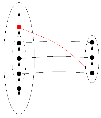
Figure 6: `Wrap-Around' of a Representation Function
For an example of a function with wrap-around, consider the following attempt to represent days of the week in two bits. Bit sequences are ordered, as shown in the DR on the right of Figure 7, below. So are days of the week, as shown in DS to the left. If the order on the bit sequences in DR is enumerated using the hardware increment function, then the value of the increment function applied to the bit sequence 11 is actually 00. Wrap-around means that, although the order is correctly implemented on what is taken to be the reachable domain, namely Monday through Thursday, the order cannot be implemented by the increment function on the natural extension of the reachable domain (namely, including Friday through Sunday), because its value on 11, the largest bit sequence of the four, is the smallest sequence (although it does agree with the order on 00, 01, and 10, correctly giving the next largest sequence). This would mean to the program that the day following Thursday is Monday, which is incorrect. To the program, whatever the day following Thursday is, it is out of the reachable domain, and it certainly cannot be Monday, which is inside the reachable domain. This wrap-around phenomenon is called `rollover' when it happens with dates.
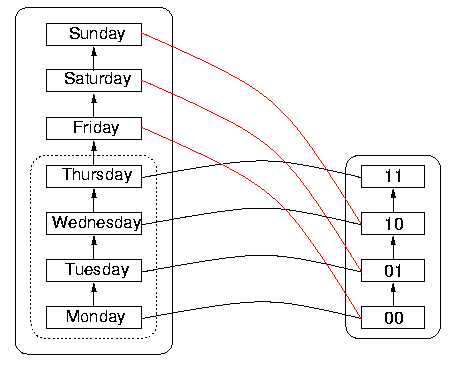
Figure 7: An Example of Wrap-Around with Dates, "rollover"
It is interesting to observe that the DS itself has wrap-around, namely that incrementing Sunday gives Monday in the normal scheme of things. But the DS wrap-around, which happens after 7 items, is out of sync with the DR wrap-around, which happens after four items rather than after seven. So Sunday rolls over to Monday in the DS on the left, but before that happens, the sequence 11 in DR representing Thursday `wraps around' to 00 again, so 00 appears to represent both Monday and Friday. Since 00 represents more than one date (as do the other sequences in fact, as a consequence of the wrap-around), the function is not one-to-one. The danger is that the reachable domain will have been imperfectly specified by the programmer or designer, so that a user could calculate with values outside the nominal reachable domain, without realising that heshe is doing so, and assuming everything is in order.
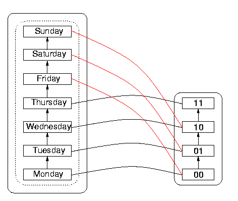
Figure 8: An Example of "Unsynchronised" Rollover
In practice, we cannot reasonably anticipate the exact domain of the representation function, because we can't predict exactly how a program will behave (in fact, there's a mathematical proof that there are programs for which it is impossible for us to so predict). So rather than calculating the domain, it is much more practical to delimit a domain which includes, but is not necessarily identical with, the domain of the representation function for P. Let us call this the reachable domain of P. It is not unique - it is the product of an informed guess, and two different people may guess differently. But we should require that such a guess be specified for each program used. In the limit, when one knows nothing, one can simply guess that all of the data structure constitutes the reachable domain, but if this structure is infinite, one is thereby guaranteed that somewhere in the reachable domain the problems which we describe will occur. To avoid data representation problems, the reachable domain must at least be finite; in fact, no larger than the set of representations. For example, if we are using 8-bit representations (see above), we must have no more than 2056 data in the reachable domain, otherwise somewhere in the reachable domain we will have some of the problems we describe.
We have seen that data representations must be functional and bijective on the reachable domain, as in Figure 4. We have also seen that one must estimate the reachable domain to be at least as small as the set of available representations. But that's not all. We shall also require that the structure of the data be preserved.
Back to Contents
Preserving Structure
What is the structure of the data that has to be preserved? Let's restrict ourselves to dates, that is, to days. Days may be written in the TUS form [1999, 3, 21], or in the form 1999-03-21 which we will use here for convenience. The structure is fairly simple: one day either precedes or follows another. One can determine which is which by comparing the dates year-to-year; then, if the years are the same, month-to-month; and if the months are the same, day-to-day. If the days are then the same, they are the same date. For example, compare 1998-02-11 with 1999-03-21. The year in the first precedes (is a smaller number than) the year in the second, so the year-to-year comparison shows that the first date precedes the second. Comparing 1999-03-21 with 1999-02-11 gives the same years, but then the month-to-month comparison shows that the second (February) precedes the first (March). Finally, comparing 1999-03-14 against 1999-03-21 gives the same year and month in those comparisons, but the day-to-day comparison shows the first precedes the second. This sequential element-by-element comparison of two data which are sequences gives the so-called lexicographic ordering of dates, so named because it is the same procedure which leads to the dictionary order of words, achieved with a character-to-character comparison: "fish" succeeds "fight" because the third element (character) of "fight", namely "g", precedes that of "fish", which is "s".
We can see that, to each day such as 1999-03-21 there is a unique day immediately preceding, in this case 1999-03-20 and a unique day immediately following, namely 1999-03-22. (Immediately before 1999-03-1 of course comes 1999-02-28, which for other years could be yyyy-02-29 if yyyy is a leap year, which leads to bookkeeping intricacy; similarly, for an arbitrary month yyyy-mm-01 the preceding day could be -31, -30, -29 or 28, and the preceding month is -12- if mm is 01. The rules are a little complicated. Let us not even think about leap seconds.) Abstracting from the actual numbers used, the days are simply ordered, with one day following the next, always with some day immediately preceding the one we're on and some day immediately following (we shall assume that the origin of time, if such there be, is not in the reachable domain). This structure can be visualised as on the left of the diagram below, with the arrows showing the succession. This simplified visual structure is all we need to illustrate the problems that arise. The visual form, what mathematicians call a directed graph, represents what they call a discrete linear order, namely a set of data in which each datum either precedes or follows any given other datum, and in which there is a unique immediate predecessor and a unique immediate successor to each element (except perhaps the first or last elements, if there are such).
The data representation must also somehow exhibit this structure. Bit patterns have a `natural' ordering themselves - in fact, the lexicographic ordering of bit sequences is the same order that one gets by considering the bit pattern to represent a whole number in binary notation, and then using the greater-than order on these numbers. One can in general define complicated relationships on the bit patterns to obtain the kind of ordering one desires: when one represents real numbers as so-called `floating point' numbers (actually bit patterns), the greater-than ordering on the real numbers is obtained through a rather more complicated order on the bit patterns. But it nevertheless has the same features that we're describing here.
The data representation function DRep must also preserve the structure of our data. That means we must define an ordering on the representation (say the lexicographic order on bit patterns) which has the same sort of properties as that of the data structure (in this case, a discrete linear order), and DRep must preserve this structure, that is, if datum e follows datum d, then pattern DRep(e) follows DRep(d) and vice versa. We can see that this is prima facie likely in the case of dates, since the lexicographic order on dates and the lexicographic order on bit patterns are both discrete linear orders. But things can go wrong, and here's how.
Back to Contents
Iterated Representation
Computer systems are not always built so that the data structures in a program are represented directly by the computer hardware, as we noted earlier. Source programs in high-level languages are usually translated into a lower-level language (often called an `intermediate' language, and these into an even-lower-level language before the hardware becomes involved. This situation is illustrated in Figure 9.
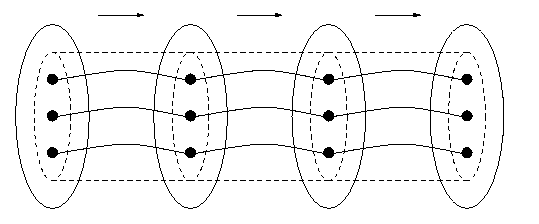
Figure 9: Iterated Representation
Back to Contents
Some More Problems
Besides those we have seen, additional problems arise from violating the four conditions of data representation, which as we have seen are
- the relation DRep is a function on the reachable domain;
- the function DRep is total on the reachable domain;
- the function DRep is one-to-one on the reachable domain and on its image;
- the function DRep preserves the structure of DS and DR on the reachable domain
Totality
The first condition requires not only that there is a unique representation that corresponds to the datum, as we saw in Figures 5-7, but also that to every datum there corresponds a representation. Because functions such as "Successor" on DS are typically implemented by structural similar functions, such as "Increment in DR, the possibility may arise that operations on DR items using, for example, Increment may yield a value that is out of DR. Although this situation is mathematically not to be desired, it may require unreasonable resources to avoid it, given the stringent constraints on computer architecture. Accomodation is often a preferable strategy to avoidance.
In well-designed data representations such as the IEEE standard for microprocessor floating-point arithmetic, there is an explicit value NotANumber which is returned when there is no `normal' representation which corresponds to the result of an operation performed on normal representations, often because one has run up against the size limitations of the representation. NotANumber can be termed an exception value. Sometimes NotANumber can itself be more finely categorised into Overflow and Underflow, which may give a user some further information on how the NotANumber arose during a calculation. Since not all data structures are number systems, one can call a general exception value NotADatum (and also consider whether it is worthwhile to consider many exception values rather than just one). If evaluating DRep on a datum D yields NotADatum, then there is no `valid' representation corresponding to D, and mathematicians would say that D is not in the domain of the function DRep. This situation is shown in the following Figure 10.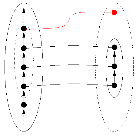
Figure 10: DRep(someDatum) is a NotADatum
The appropriate steps to take to ensure that this situation is correctly handled are either
- to prove that for no datum d in the reachable domain is DRep(d) = NotANumber (avoidance); or
- to provide appropriate exception handling for cases in which DRep(d) = NotANumber (accomodation).
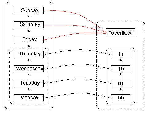
Figure 11: Rollover Handled Using NotADatum
This example shows that having DRep yield values that are NotADatum on items outside of its specified reachable domain can be a good idea. DRep remains one-to-one on the reachable domain, and the program is given a clear indication that a data item not supposed to be reachable has been reached. However, it remains for the program to handle the `exception condition', the overflow, correctly. An example of what can happen when overflows are not appropriately handled is given by the Ariane 501 flight disaster, analysed in The Ariane 5 Accident: A Programming Problem?, Report RVS-J-98-02 by Peter Ladkin.
Back to ContentsOne-To-Oneness
The second situation, that DRep is not one-to-one, can be subsumed for the case of ordering under Structure Damage, considered in the next section. To see that this is so, consider the following reasoning. DRep(d) = DRep(e) for two distinct data d and e. In this case, we are considering discrete totally-ordered domains, and since d < e and it is not the case that DRep(d) < DRep(e), this situation also entails that the condition of structure preservation has been violated. This conclusion may not invariably follow for domains which have other structure than a discrete total order, so we illustrate it separately from structure violation. The problems arise when an application program tries to determine which datum is specified when a given representation is produced. One cannot determine whether d or e is meant. The representation is thus ambiguous. The year-representation part of the Year 2000 problem can be considered an example of this. A program or algorithm using a two-decimal-digit year representation cannot determine in general whether "00" represents "1900" or "2000" and calculations can thereby become radically incorrect. The solution is to determine at program development time that to each representation corresponds a unique datum. Notice that if the size of the reachable domain exceeds that of the representation, and if the operation that increments an element of the domain corresponds to an operation which always returns a `valid' DR value (and not NotADatum), then it is inevitable that some two data will obtain the same representation. This is an application of what mathematicians call the `pigeon-hole principle', that if there are more X's than Y's, and to each X corresponds a Y, then some Y will correspond to more than one X. The names come from considering Y to be a collection of mailboxes (or `pigeon-holes'), and X to be a collection of letters all with addresses in Y. Some mailbox must contain more than one letter after all have been distributed.
The avoidance of such problems is explicitly to ensure one-to-oneness at system development time: that to each representation corresponds a unique datum. This is unobtainable under the two conditions that
- the size of the reachable domain exceeds the size of the representation domain; and
- the reachable domain may be enumerated by an operation to which corresponds an operation in the representation domain that always yields a value.
Structure Preservation
The third kind of problem occurs when the structure, in this case the discrete order, is not preserved between the data structure and the representation. In the case of a discrete linear order, this would mean either that, for some B, the successor of some datum A, it is not the case that DRep(B) is the successor of DRep(A), but that some other element C is; or vice versa, that for some pair of items in DR of which one is the successor of the other, their correspondents in DS do not stand in the relation of successor to each other. Mutatis mutandis for "predecessor". These situations are represented in the following Figure 12, which we explain below.
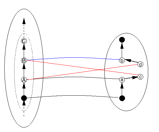
Figure 12: Structure of the Order is Not Preserved
Let us use the name "Successor" for the DS operation that advances a DS item to the next one in DS, and "Increment" for the DR operation that advances a DR item to the next one in DR. The term "structure preserving" means that Increment is supposed to implement the Successor function. In Figure 12, if c isn't the same as b, and d the same as a, there's trouble. Here's how. The next DS item to follow A is B, whose representation is b (that is, DRep(B) = b). So if the program advances from A to Successor(A) (that is, B), it `expects' that its representation (that is, DRep(B)) will be Increment(DRep(A)). So to keep everything straight, we need these two to be the same: DRep(B) = Increment(DRep(A) Now DRep(B) = b and Increment(DRep(A)) = Increment(a) = c, so if b and c aren't identical, we've got trouble.
Similar reasoning can be performed concerning "Predecessor" (which is the function that gives the last item before the current one. So Predecessor(B) = A and Predecessor(C) = B. The similar function on the DR side can be called decrement, as it is in most computer hardware. We can follow similar reasoning as above to conclude that if a and d aren't the same item, there's trouble. What is not shown in Figure 11 is that similar kinds of trouble must inevitably follow for all items following B - this fact follows mathematically from the situation that b and c are not identical, but we don't need to show how here.
`Extra' Items in the DR Ordering
One of the easiest such concrete situations to grasp is one in which there is an additional element in the order DR that does not appear between the appropriate two elements in DS. This situation is illustrated in Figure 13 (in which we leave out the NotADatum area on the DR side for visual simplicity). The interpretation of Figure 13 in terms of the situation in Figure 12 is to take
| X | as | A |
| Y | as | B |
| x | as | a |
| y | as | b |
| y | as | both c and d |
(which in this particular instance will be the same).
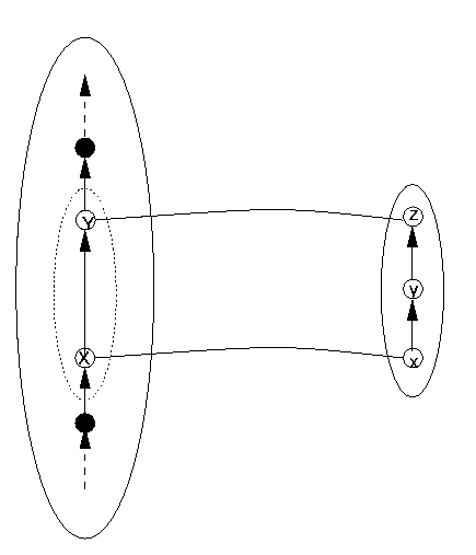
Figure 13: A Simple Structure-Damaged Situation
`Extra' Items in the DS Ordering
Because the function DRep is supposed to be one-to-one and total, there is equally damage if a similar situation happens in the other direction: DS has an element whose representation is skipped in DR. This situation is illustrated in Figure 14. There is, however, a slight difference which makes the situation not quite symmetrical. The DS item Y has no direct representation on the DR side, so in fact the function DRep is not total. Thus two problems arise in the case in Figure 14: structure damage and an intotal DRep. Figure 11 was drawn assuming DRep was total on the reachable domain, to illustrate structure damage alone. However, the line from Y to y (= DRep(Y)) in Figure 12 was drawn in blue to highlight the situation we describe in Figure 14, in which not only is structure not preserved, but DRep is not total.
The interpretation of Figure 14 in terms of the situation in Figure 12 is to take
| X | as | A |
| Y | as | B |
| Z | as | C |
| x | as | a |
| y | as | c |
Because there is no representation of Y in DR, DRep has no value in DR corresponding to Y, and thus the blue line from Y to y in Figure 12 does not appear in Figure 14, because it does not exist in this case. That also means that we have no interpretation for b and thus no interpretation for d either.
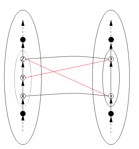
Figure 14: The Symmetric Structure-Damaged Situation on the DS Side
Leap Year Miscalculations
The situation in Figures 13 and 14 is illustrated concretely by another facet of the Year 2000 data discontinuity problems, namely failure to account for the 29th February. The potential situation concerning the leap year 2000 actually occurred with some systems already in 1996. The failure to account for the 29th February 1996 led to the emergency shutdown of two aluminium smelters, in New Zealand and Tasmania. They shut down at midnight on December 30th, 1996, because dates were represented as number of days since the beginning of the year, and when the systems reached Day 366, there was a problem, because it wasn't the first day of 1997, but still in 1996. This should remind us that the first manifestations of a problem may occur long after the problem has arisen. And who knows what date-dependent data has been corrupted in the meantime.
A leap-year problem can occur either according to the scheme in Figure 13 or to that in Figure 14. Figure 13 indicates what happens when applications software (DS) forgets a date that the operating system or hardware (DR) `remembers'. Figure 14 indicates what happens when the hardware (say, an embedded system clock/calendar) is unaware of the leap day, but the higher-level program is aware of it. We do not know exactly which of these two situations occurred to the aluminium smelters in the Antipodes. We also note that the situation does not happen only on the level of days. In certain years, a leap second is added to the middle of the year to align the time according to atomic clocks with solar motions more precisely. Since the decision to add a leap second is made only a relatively short time beforehand, the situation described by Figures 13 and 14 occurs relatively often. In this case, though, there are algorithms such as the Network Time Service (NTS) which allow the calendar programs synchronised with the hardware clocks of networked machines to readjust themselves within certain limits to outside time signals. Also, the disturbances to systems caused by extra seconds affect quite different sorts of computer use from those caused by unforeseen leap days. They won't affect accounting software systems, for example.
The leap-year structure violation is illustrated in Figure 15 (in which we have written DRep(02.28) also as 02.28 in DR, and other dates similarly, we hope without confusion ensuing). The structure-damaging connection between 02.29 on the DS side, and DRep(03.01) in DR is shown as a dashed blue line; respectively on the DS side as the successor of 02.28, and on the DR side as the increment of DRep(02.28). We have not included the year, because in principle this situation could occur for any leap year which has not been considered as such by the designers of the program.
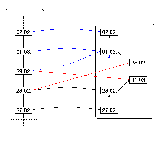
Figure 15: The Leap-Year Miscalculation
In this instance of structure damage, the interpretation of the nodes in Figure 13 is as follows:
| X | = | 2000.02.28 |
| Y | = | 2000.02.29 |
| Z | = | 2000.03.01 |
| x | = | DRep(2000.02.28) |
| y | = | DRep(2000.03.01) |
Rollover as Structure Damage
Finally, we should point out that the rollover problem mentioned earlier is also an example of violation of structure:
- successor(1999-12-31) = 2000-01-01
- successor(DRep(1999-12-31)) = 00-01-01
- date-of(00-01-01) = 1900-01-01; therefore
- successor(date-of(DRep(1999-12-31))) not = successor(1999-12-31)
This situation occurs because the successor operation in the representation is always defined - but leads to a `loop'. The directed graph of `successor' in the data representation is in fact a cycle; further, this cycle lies entirely in the image of the reachable domain of the data structure under DRep! This clearly violates the properties of a discrete linear order.
Back to ContentsVerification Conditions
It seems to be that most scientific work in verification of computer systems has concentrated on verification of algorithms and the dynamics of systems, possibly because this aspect of the correctness of programs is so very hard. In contrast, the verification of data structure representations is relatively straightforward to describe, as we have seen, and often quite straightforward to implement. The most complicated common case is probably the implementation of real numbers using floating-point arithmetic, and indeed some notable mathematicians (including one Turing Award winner, William Kahan of the University of California, Berkeley) have worked on the correct implementation of real number arithmetic. One might say that there seems to be no ideal solution to this particular data structure representation problem, although there are solutions involving careful evaluation of terms and careful exception handling which are satisfactory.
To summarise, the verification conditions for adequate data structure representation are:
- For the program P, an adequate reachable domain Reachable(P) has been calculated;
- DRep is a function on the reachable domain;
- DRep is total on the reachable domain;
- DRep is one-to-one on the reachable domain and its image;
- DRep preserves the structure of the reachable domain
- DRep is an isomorphism of the reachable domain onto its representation
And each of these five conditions is violated by some instance of what have been grouped together as `Year 2000 problems'. What conclusion may we draw?
General Data Structures
The general conditions listed above for correct data representation are completely general. However, we have based our analysis in the Section "Structure Preservation" upon data structures which are linear orderings of items. Many of the most common structures, such as dates or numbers, are indeed linear orderings. However, many of them, such as complex numbers or records (which are like "mini databases", containing many heterogeneous items) are not. For such data structures, the condition of `preserving structure' will not take exactly the same simple, picturesque form that it does for linear orderings, because the structure of data is different, and usually more complex. There is a logical definition of `preserving structure' which is general, and applicable equally to linear orderings and complex data structures. But we consider that it would be beyond the scope of this paper, and perhaps also of our readers' tolerance, to describe it here in more detail.Is Verification Worth It?
It used to be said that program verification was too expensive for practical use in software development. Various estimates now put the cost of dealing with the Year 2000 issues, including determining for a given system whether there are Year 2000 problems or not, at about $300-600 billion world-wide (estimate from the Gartner Group, quoted by the OECD on their WWW page The Year 2000 Problem) up to $3.6 trillion (Capers Jones, estimating pre-2000 repairs plus post-2000 damage control and repair, in interview with The Millennium Journal, V.V, May 1998. The actual cost may vary but is unlikely to be lower than the Gartner Group's lowest estimate of $300 billion. Had the (in this case) relatively simple data structure verifications been performed during software development, we would have no Year 2000 problem and this $600 billion would have been saved. We can hardly believe that it would have cost world-wide more than this sum to have verified the software in the first place, because it is well-known that reverse engineering costs more than forward development, and the costs of Year 2000 checks are almost all reverse engineering. We hope that software developers will no longer have the temerity to claim that verification at development time costs more than fixing the inevitable problems later. The Year 2000 problems stand as clear counter examples to this claim.